Pro Whip 80

After the March Saturday Session many of you may have noticed my vertical on the back of the Land Rover had snapped in the high winds.
While I was rebuilding it I thought I'd capture the detail of this aerial build as Pro Whip is no longer in business. Basically my vertical was marketed as an 80m - 10m vertical "requiring an ATU for some bands" e.g. most of the bands! It definitely isn't the best aerial known to man but it's better than the mobile whip on my car and can be erected in just a few minutes.
In simple terms the aerial is ~20m dipole fed through a 4:1 balun help it present a more acceptable impedance match on other bands. I must try it on 20m without the balun as it would probably give me a better match!
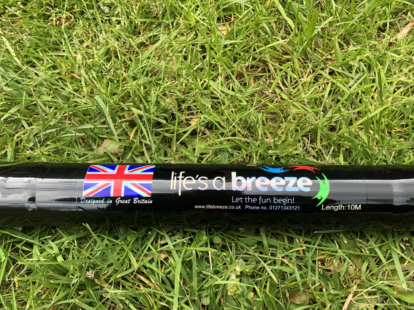
This aerial is boult around a 10m telescopic fibreglass pole. I've used a basic one from Life is a Breeze as they are quite sturdy. They actually make a heavier duty model than the one I bought but it may be a bit of an overkill for a vertical aerial. This was about £45 once you add delivery. There are cheaper options out there but they may be less robust. My only niggle with this particular pole is the end caps come off very easily.

The aerial has two elements; the vertical radiating element which passes up through the centre of the pole and a counterpoise which lays on the ground.
The radiator and counterpoise are both ~10.25m in length. The red (in my pictures) radiator wire is a very flexible 'rubber' coated equipment wire whereas the counterpoise is a standard PVC coated wire. The reason the radiator needs to be super flexible is because the base has a ~8mm hole cut in it. As you extend or contract the pole the wire needs to be flexible enough to simply 'fall' through the hole without kinking and getting stuck.
Before I passed the radiator up through the centre of the pole it was necessary to remove the metal cap and loop fitted to the tip of the pole. This is just glued on so I used a lighter to heat it us and then twisted it off gently with a pair of pliers (careful...it's hot!).
With that done I stripped a few centimetres of insulation off the wire, pushed it up through the centre of the pole so that it poked through the end of the smallest top section then I folded the stripped cable over the end a used a bit of heat shrink to fix it firmly in place.
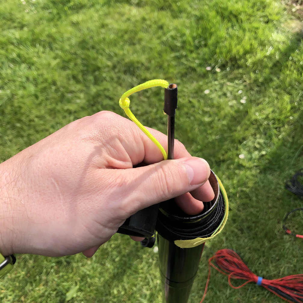
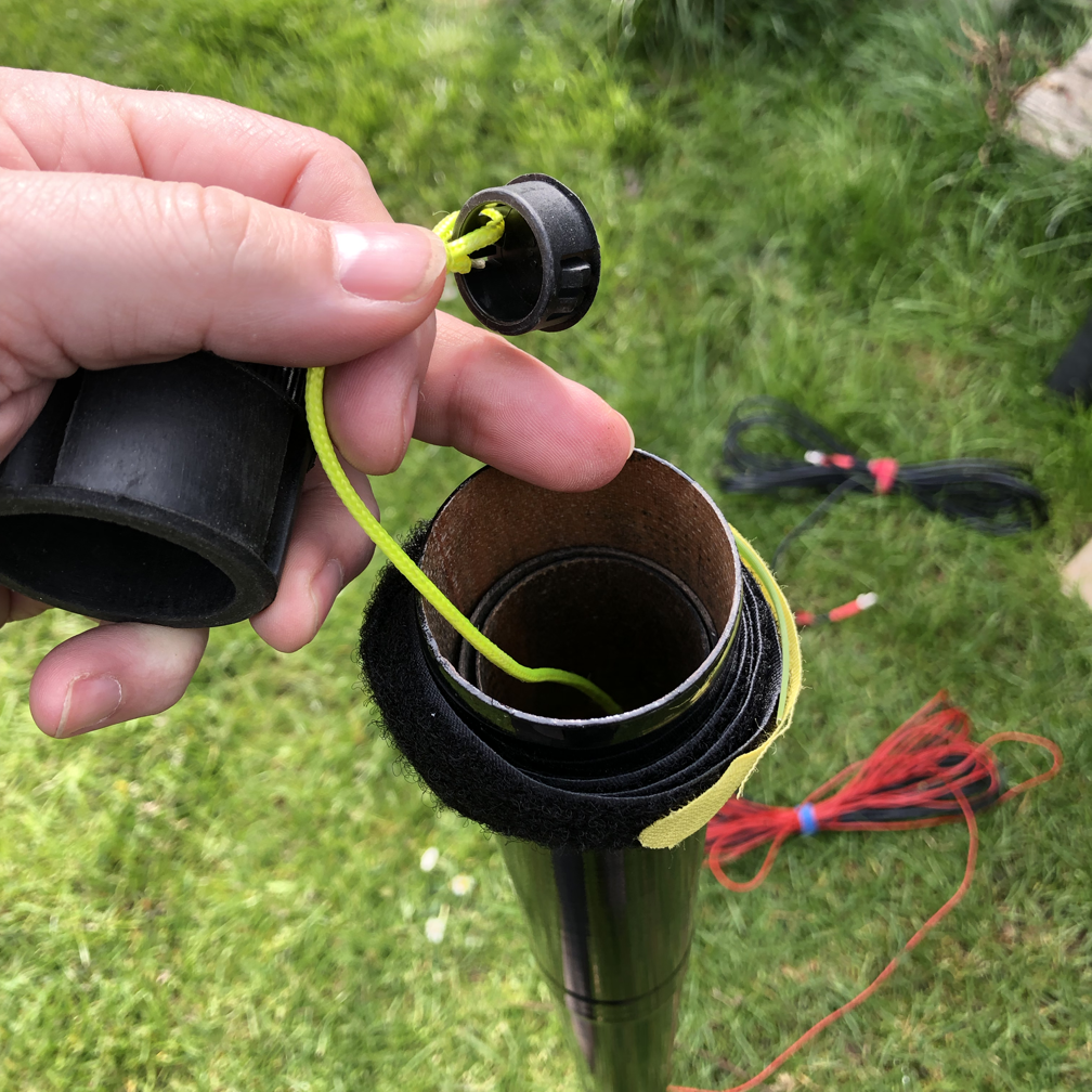
A little trick I use on a lot of my telescopic poles is to also heat shrink a short length of 'string' to the end of the pole and to tie something to the end that is big enough to grab but small enough to fit inside the outer pole with the rubber end cap on when the pole is contracted. It simply makes getting the tip section out to start erecting the aerial a bit easier.
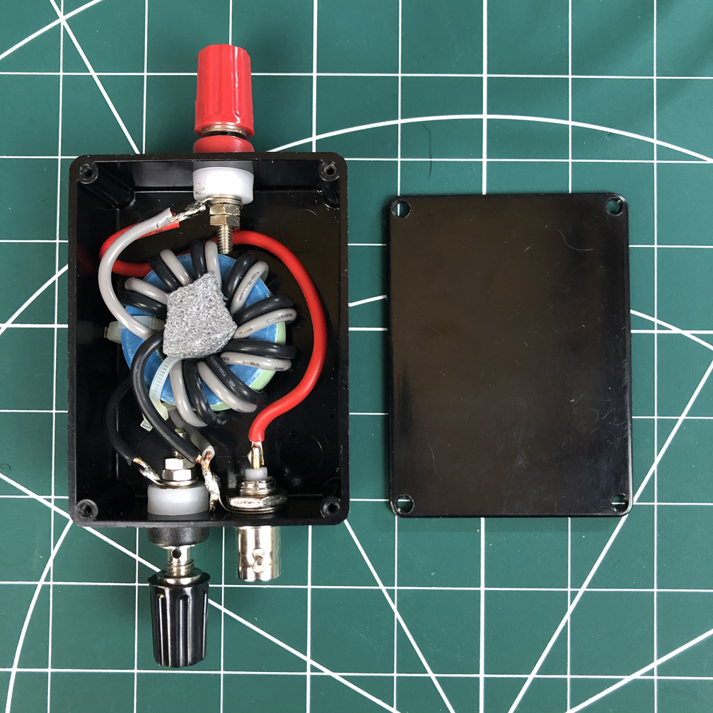
The balun appears to be a basic 4:1 voltage balun. I can't tell you anything about the toroid other than it is about 32mm outside diameter but there are lots of online guides to making 4:1 baluns with the full details of the cores to use. This one is quite a big toroid and wound with quite heavy wire as the original aerial was designed for 100W. I could easily down size this for my QRP operation however, my only reason for breaking open the original sealed balun was so that I could replace the SO-259 with a BNC socket.
I've refitted the toroid in a small 75 x 55 x 25mm box that I happened to have but it did mean putting one of the binding posts on top. It would be more practical to have the BNC/SO-259 and binding posts on the bottom face together.

The balun box simply uses some velcro pads on the back to attached to similar stuck to the base of the aerial to keep things nicely secure. The radiator should be just long enough to come out of the base of the pole and wrap around to the balun box with the counterpoise lated on the ground connected to the other balanced input connector.
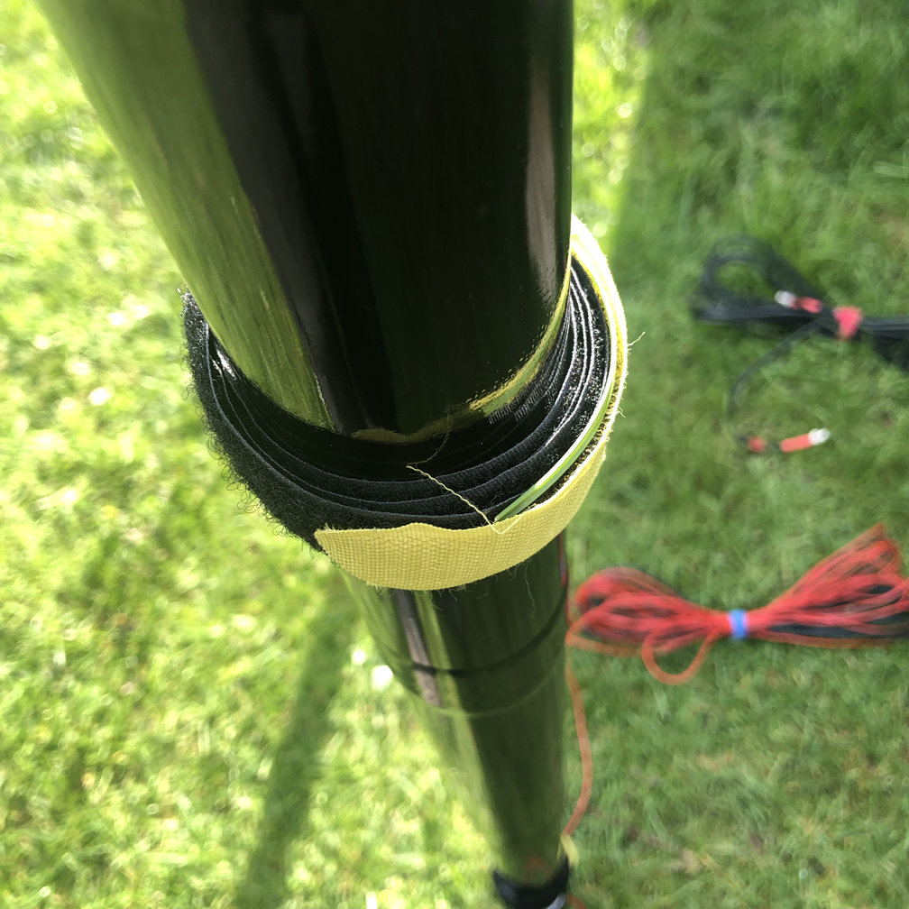
Because the radiator passes out of the bottom of the pole it helps to mount it by strapping it to something off the ground. I have a couple of long velcro straps for this which can be used to strap the pole firmly (but without applying pressure to acutely) to a fence post or, in my case, the ladder on the back of my Land Rover.
My build is naturally resonant at 4.1MHZ, 6.2MHz, 20.4MHz, 34.2MHz, 48.4MHz & 54.7MHz.
With no ATU and only a few metres of coax attached I can use it on the following bands:
80M - 2.2 to 1.7:1 across whole band
60M - 2:1 across whole band
40m - 2.5 to 2.8:1 across whole band (not great!)
17m - 2.2:1 across whole band
15m - 1.4 to 1.7:1 across whole band
10m - <2.7:1 across whole band
6m - <1.5:1 across whole band
I must try it without the balun as that should get it working on 20m. Obviously with an ATU I can encourage it to match on the other bands and improve the matching on the bands listed above.

Schematic of the balun
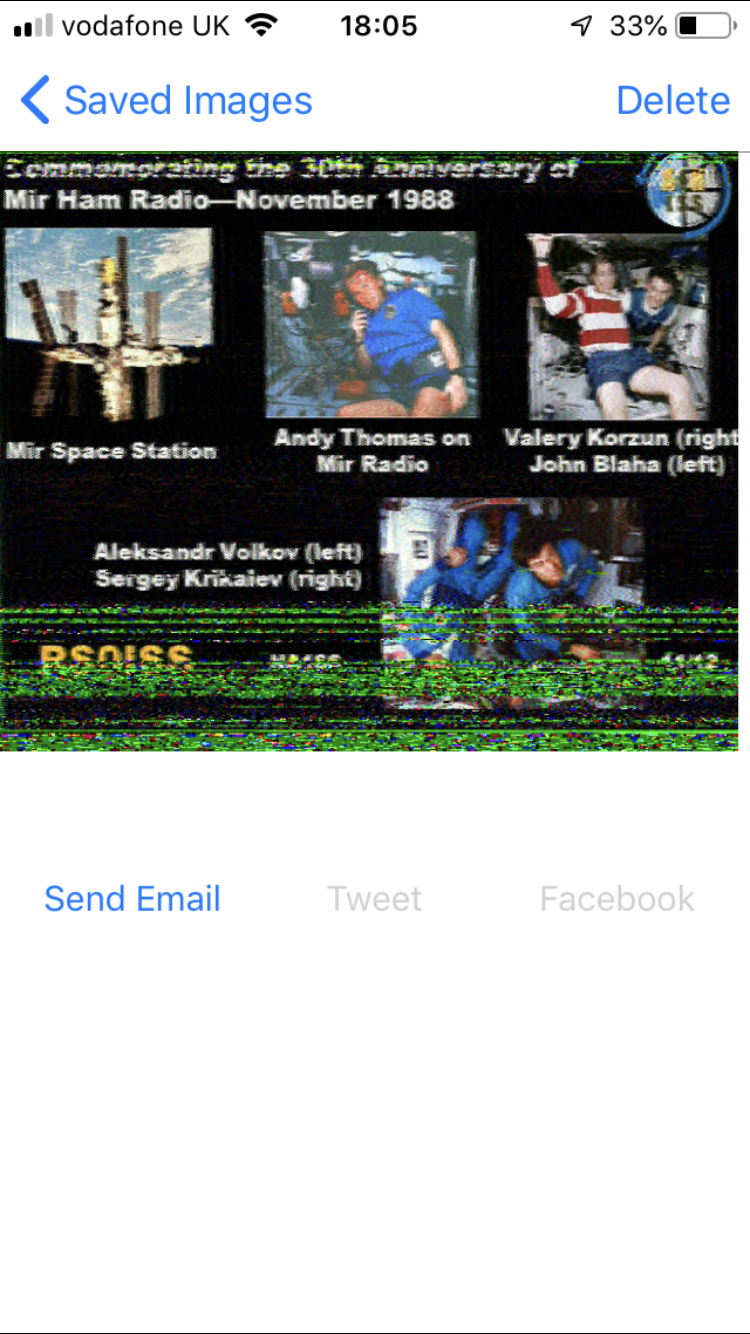
SSTV from the ISS
During the session we had a go trying to decode the SSTV transmissions from the ISS quite simply using a handheld (tuned to 145.800MHz FM) and an app on my iPhone.
The apps I was using are;
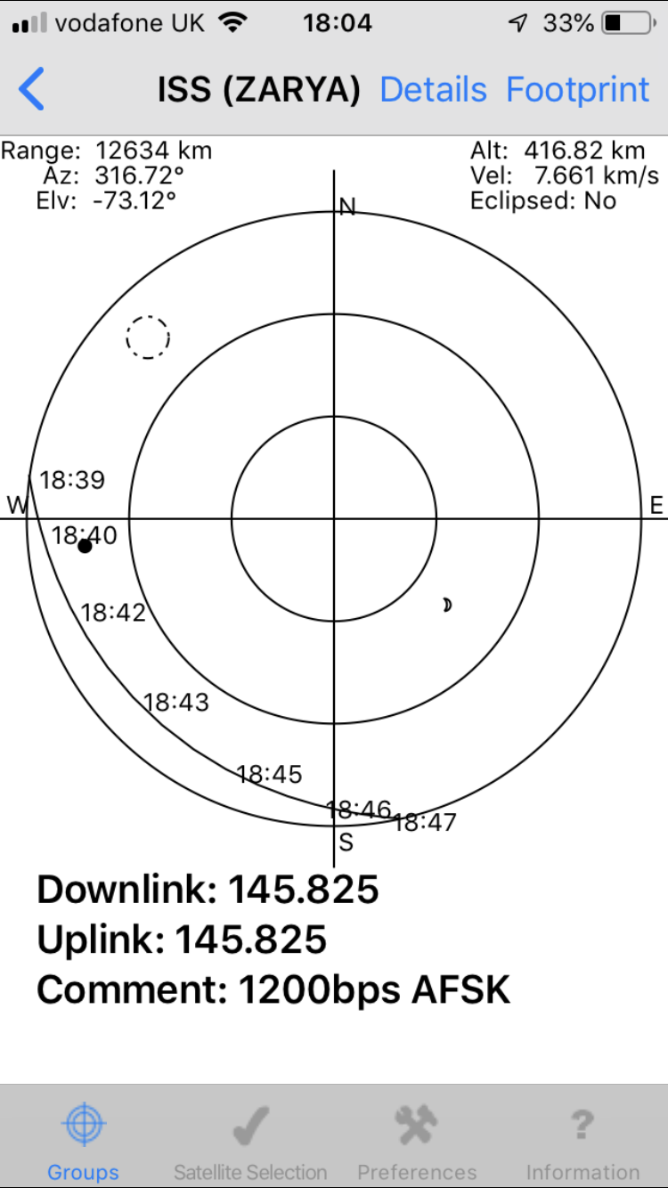
Satellite Tracker Plus v3.1 from Suzan MacKay (VK3ANZ) (developer: MacCon)
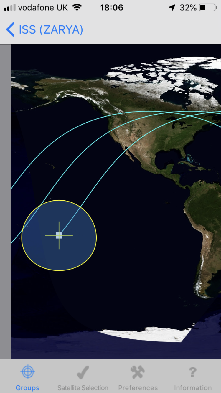
A nicely featured satellite tracker that lets you choose your satellites of interest from a list and create groups (like FM Sats, SSB Sats, etc). It shows you the path and height of the satellite for the next pass and the times for AOS and LOS (acquisition/loss of satellite) for the next few dozen passes. You can also view the footprint of the satellites coverage in a graphical map. It has a handy feature that allows you to use your phone as a 'pointer' to establish the satellite position in the sky.
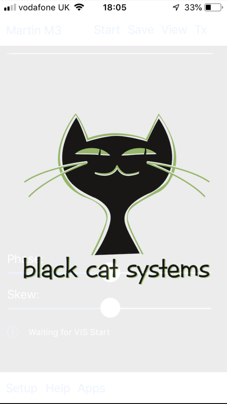
SSTV from Black Cat Systems (developer: Black Cat Systems)
A super simple SSTV application which allows you to send or receive SSTV images using up to 40 different encoding schemes or their variants.